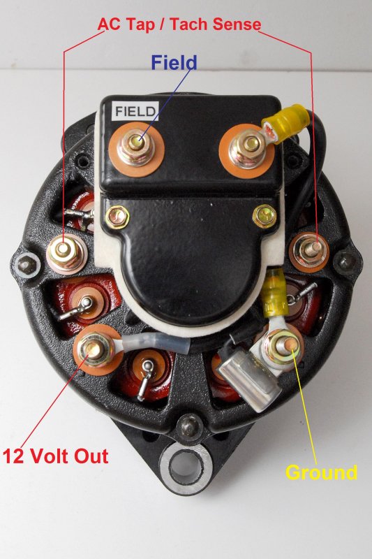
Marine Alternator Wiring Diagram Alternators Voltage Sensing Marine
A diagram of an alternator, showing the various components and how they work together to produce electrical energy for a vehicle or generator. Learn about the different parts, such as the rotor, stator, diodes, and voltage regulator, and understand how they function in converting mechanical energy into electricity.
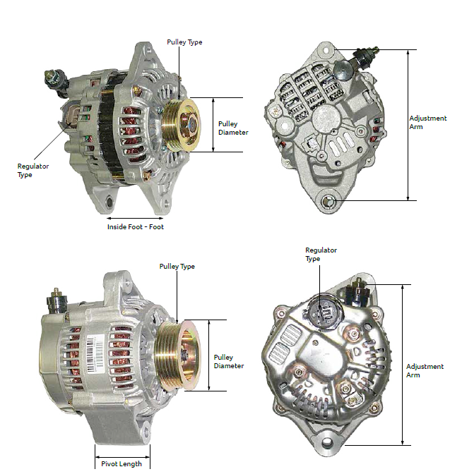
Alternator Application Guide The Parts Man
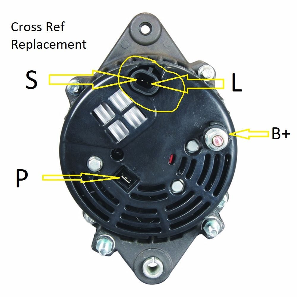
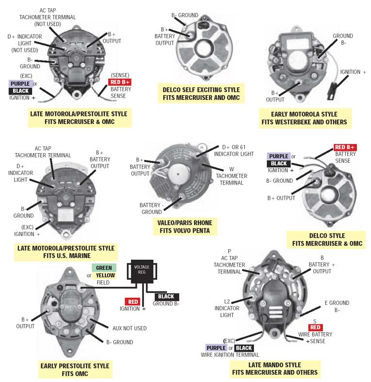
Identify the wiring connections: Identify the four wires on the alternator - typically labeled as "B," "L," "P," and "S." Referencing the wiring diagram, determine which wire corresponds to each connection. Connect the "B" wire: The "B" wire is the main power wire that supplies electrical current to the alternator.
Lucas 3 Wire Alternator Wiring Diagram For Your Needs
4 Wire Alternator Wiring Diagram is the linchpin of a vehicle's electrical system, seamlessly connecting components from the GM to Delco. It ensures an efficient conversion of alternating current from the alternator to direct current for your battery, harmonizing the electrical demands of any car, whether Ford or Chevrolet.
Gm 5 Wire Alternator Wiring Diagram
Let's take a closer look at the 12 volt alternator wiring diagram. The diagram consists of three main components: the alternator, the voltage regulator, and the battery. The alternator has two main parts - the stator and the rotor. The stator is a stationary set of wire coils, while the rotor is a rotating magnet that spins inside the stator.

Lucas 18 Acr Alternator Wiring Diagram
Alternator Overview The alternator contains: A rotating field winding called the rotor. A stationary induction winding called the stator. A diode assembly called the rectifier bridge. A control device called the voltage regulator. Two internal fans to promote air circulation.
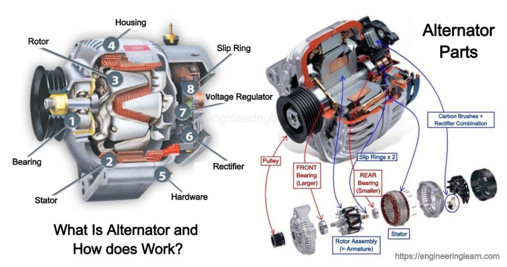
What Is Alternator and How does Works? Engineering Learner
How does an Alternator Work? Let's look inside an alternator and examine all of its individual parts. In this article, we're going to talk about a major component of many electrical power or charging systems, the Alternator. In particular, we're going to look closely at a typical vehicle alternator. How an Alternator Works: The Ultimate Guide

Nikko Alternator Wiring Diagram
Fig. 1: Portion of an alternator stator The magnetic core of the Stator is built-up of special steel stampings insulated from each other with paper, varnish or oxide coating. These laminations are in the form of complete rings for smaller machines and in segments for larger machines.

Difference between Generators and Alternators
A basic alternator is made up of a series of alternating finger pole pieces placed around coil wires called field windings that wrap around an iron core on the rotor shaft. Since we know the pulley attaches to the shaft, we can now visualize how the rotor spins inside the stator.

fr v alternator wiring diagram
Figure 1, below, is a block diagram, or a "functional" diagram, of an alternator, and its connections to the remainder of the automobile electrical system. Following the figure is a description of the various components that make up an alternator, and a description of how each operates to keep the battery charged in your car. ALTERNATOR ROTOR

What Is an Alternator in a Car? What Does an Alternator Do? How
1. What Is An Alternator For? 2. How Does An Alternator Work? 3. Alternator Wire Overview 4. Wire Alternator Wiring Diagram: What Wires Go Where? 5. What Are The 4 Wires On An Alternator 6. What Are The 4 Terminals On An Alternator? 7. How To Wire An Alternator To Charge A Battery? 8. FAQs 9. Final Thoughts What Is An Alternator For?
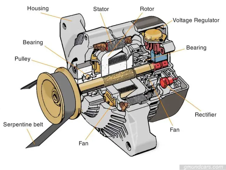
Bad alternator signs to tell and what to do? Gmund Cars
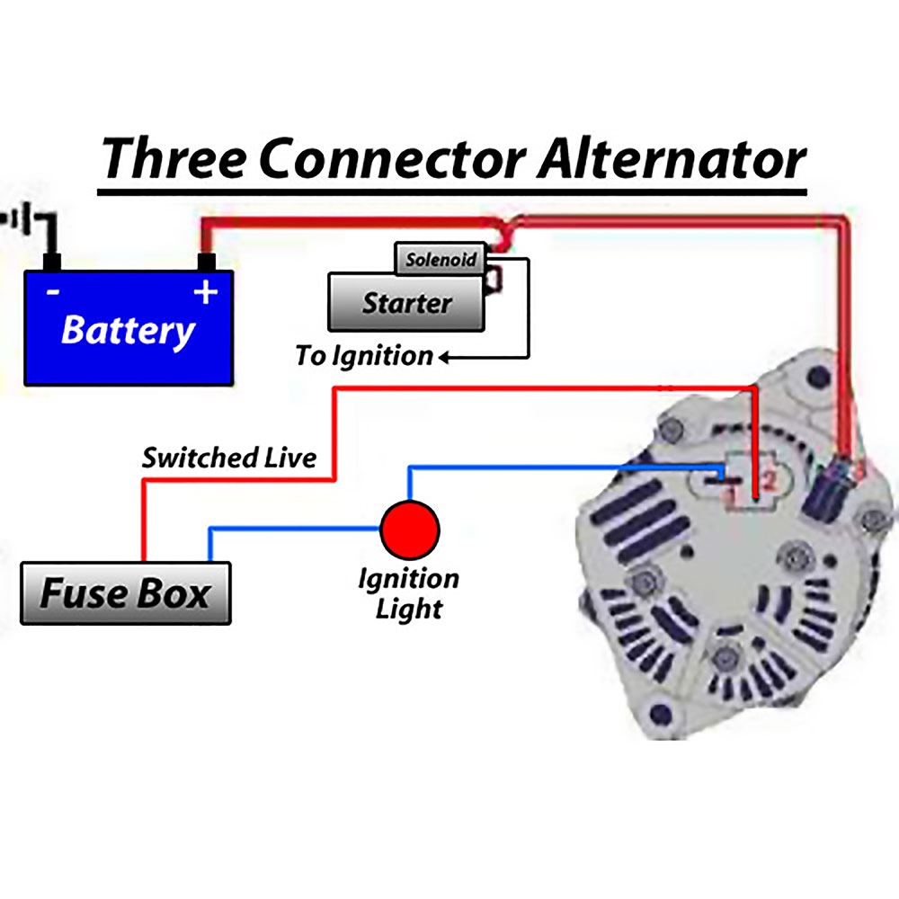
Need Help? Ask a mechanic online, 24 hours a day here: https://tinyurl.com/24-7-mechanicIn this video we'll talk about a 3 wire alternator wiring diagram, ho.

Gm One Wire Alternator Diagram
A 2 wire alternator wiring diagram shows the connection between them. Depending on the make and model of your vehicle, you can replace either of them if needed. What are the 2 wires on an alternator? You probably have asked yourself: What are the two wires on an alternator? First of all, there are two main connections.
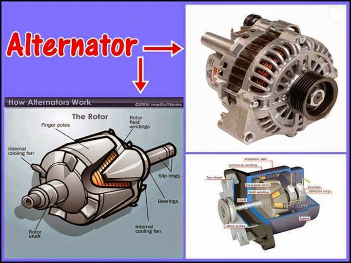
How alternators work? Electrical Engineering Pics
An alternator wiring diagram will help you get the basic know-how of the circuit and how the components are linked together in a circuit. So, without further ado, let's dive in. Do you want to know more about what is alternator wiring diagram and how to make your own alternator wiring diagram?
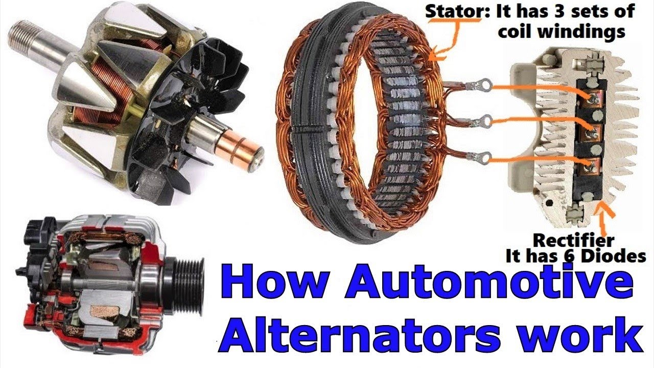
How the Automotive Alternator works YouTube
Diagram of a simple alternator with a rotating magnetic core (rotor) and stationary wire (stator) also showing the current induced in the stator by the rotating magnetic field of the rotor. A conductor moving relative to a magnetic field develops an electromotive force (EMF) in it ( Faraday's Law ).
Marine Alternator Wiring Diagram Alternators Voltage Sensing Marine
Diagram of an Alternator Circuit. Easy to read and follow. Wiring diagrams show the wiring, connectors, and other system related information. They're like road maps for the wiring routed throughout a vehicle.

Repair Guides Engine Electrical Alternator
Construction of Alternator. October 25, 2020 by Electrical4U. The construction of an alternator consists of field poles placed on the rotating fixture of the machine. An alternator is made up of two main parts: a rotor and a stator. The rotor rotates in the stator, and the field poles get projected onto the rotor body of the alternator.
